


Soil Investigation
- Field and laboratory investigation is required to obtain the necessary data of the soils for the successful construction of any structure at the site are collectively called soil exploration or Sub surface Investigation .
- The choice of the foundation and its depth, the bearing capacity, settlement analysis depend very much on the engineering properties of the soil .
The primary objectives of soil exploration are
- To assess the general suitability of site
- To Find the Bearing Capacity of the soil
- To select type and foundation for a given structure
- To Investigate the nature and depth of each stratum and assess required properties.
- To Predict possible difficulties and problems in site and suggest remedial actions
- To Select a suitable construction materials in site and suggest remedial actions
- To Study shrinkage and swelling potential
- To Study ground water conditions .
- To determine the depth and nature of bed rock
- To determine the water table and its fluctuation
Methods of exploration can be broadly classified into two categories:
Direct Method
Boring or trial pits at a predetermined location to the required depth and fairly intact samples of soils from every stratum encountered or at suitably selected depths is obtained which are utilised to get necessary information about the soil characteristics.
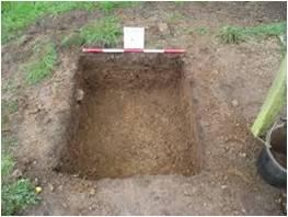
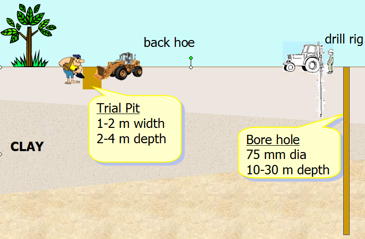
Exploration by Test pits
Pits are dug manually but mechanical equipment may also be used for the purpose up to shallow depths. In dry ground, pits are economical in comparison to bore holes up to a depth of about 5m depending upon the location. As the depth increases, the cost of excavating a pit increases very rapidly and it is seldom that unsupported pits are dug to a depth exceeding 6 m except in the case of hard soils. The top of a pit shall be kept large enough so that dimension of the pit at the bottom may be at least 1.2 m X 1.2 m which are sufficient to provide necessary working space. Additional space for sheeting and timber support, hoisting arrangements and ladder, etc. shall be provided.
For deep pits in soil, the walls shall be supported by timber. During excavation, the pit should be kept fairly level and of full section so that each lift may represent the corresponding portion of the deposit in quality and quantity. The excavated material should be placed round the pits as stockpiles, separated when significantly different materials are encountered; and marked stakes should be driven in to the stockpiles to indicate the depth from which the materials were excavated in order to facilitate logging and sampling latter on. The excavated material should be placed round the pits in the manner it is received from the excavation, preferably in a clockwise direction. The deposits of excavated material from the pit at every change in strata should be dumped separately in the manner described above. Samples from these deposits should be taken as soon as material comes out of the pots and the natural water content of the excavation material determined. Test pits left open for inspection shall be provided with covers or barricades for safety. Pits and trenches shall be suitably fenced. Trenches and pits should be filled back properly.
Exploration by Trenches
Test trenches are useful when a continuous exposure along a given line or section is desired. In general they serve the same purpose as the pit but have the added advantage of disclosing the continuity or limits of the formations or deposits in question and any vertical faults in the rock structured. The field work consists of excavating an open trench from the top to the bottom of the slope to reach representative undisturbed material. Either a single slot trench down the face of the slope or a series of short trenches spaced at appropriate intervals along the slope may be excavated. Depending on the extent of the investigation required, use may be made of picks and shovels; bulldozers, ditching machines, back hoes or dragline.

Exploration by Borings:-
When the depth of exploration is larger borings are used for exploration .
Methods of Borings (As per IS 1892:1979)
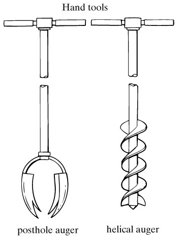
Auger boring- these are suitable for advancing holes up to a depth of 3 to 6m in soft soils
Wash boring- Used for advancing hole in the ground. This method is slow in stiff soils and coarse grained soils.
Rotary drilling- Can be used in clay sand and rocks.
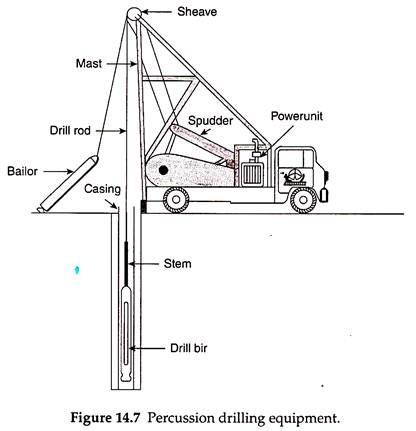
Percussion drilling- used for drilling holes in rocks boulders and other hard strata
Core drilling- used for drilling holes in rock and for obtaining rock cores( for identification and tests)
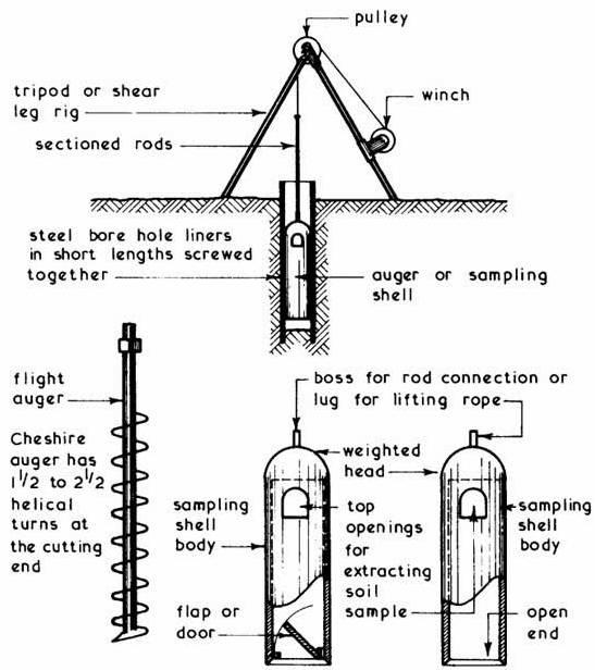
Exploration by Borings and Drilling
Hand Auger Borings - Auger boring is the most common, economical and rapid method for relatively shallow exploration of fine - grained materials above the water - table. Hand augers become awkward and cumbersome beyond a depth of approximately 6 m. If the work is done carefully, the layers of different soils may be accurately located, identified classified and suitable distributed samples obtained.
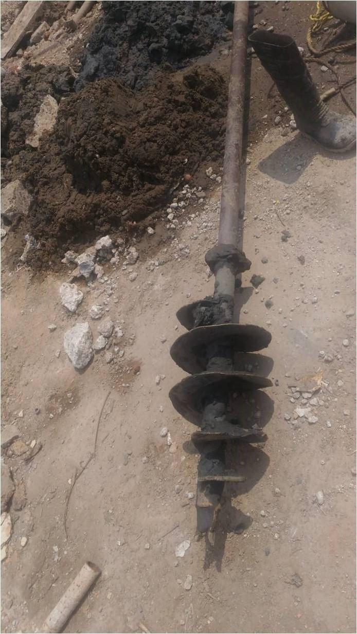
Power Auger Borings - The most suitable type of power-auger for soil investigations is the one that will drill a hole at least 60 cm. in diameter (preferably 70 cm to 90 cm), which is large enough for a man to enter and make accurate inspection or sampling of the soil in place. These large-size augers will drill into slightly cohesive soils containing appreciable quantities of gravel up to 7.5 or 10 cm in size. Power-augers are not satisfactory for use in bouldery materials.
Most augers permit boring of holes of about 2.5 m to 3.65 m depth. However, more recent equipment allow boring up to 6 m or even 12 m depths.
This type of exploration has to be resorted where the required strata or deposit in case of investigation of materials, cannot be reached by the methods mentioned above or where the compaction or the soil strata or presence of boulders and rock make it necessary.
Indirect Methods
These methods include various sounding and geophysical methods, indirectly by measuring in-situ a tool/instrument behavior during interaction with soil/rock and inference of material properties. eg. SPT, cone penetrometer etc.
Choice of method depends on budget, sampling requirements, extent of investigation, and often site conditions.
VANE SHEAR TEST
Vane shear test (VST)- to determine shear strength of cohesive soil in its natural condition.( Is 4434:- 1978)The vane shear test is most appropriate for the determination of the shear strength of saturated clays, especially of the ‘soft’ to ‘medium’ consistency.
The test is especially appropriate for determining the shear strength of sensitive soils which are highly susceptible to sampling disturbances.
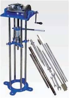
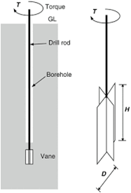
The vane shear test consists of pushing a four-bladed vane in the soil and rotating it till a cylindrical surface in the soil fails by shear. The torque required to cause this failure is measured and this torque is converted to a unit shearing resistance of the cylindrical surface
Standard Penetration Test (SPT)- to determine N-value (IS 2131-1981)
IS 2131 :1981 (Reaffirmed 1987): Indian standard – Method for standard Penetration test for soils .SPT is widely used to determine the parameters of the soil in situ .
The test consists of driving a split spoon into the soil through a borehole at the desired
depth . This test was developed in 1920 Consist of 3 parts
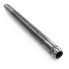
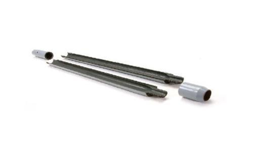
-Driving shoe at bottom- 75mm long
-Steel tube, split longitudinally into 2 halves-450mm long
-Coupling at the top-150mm long .
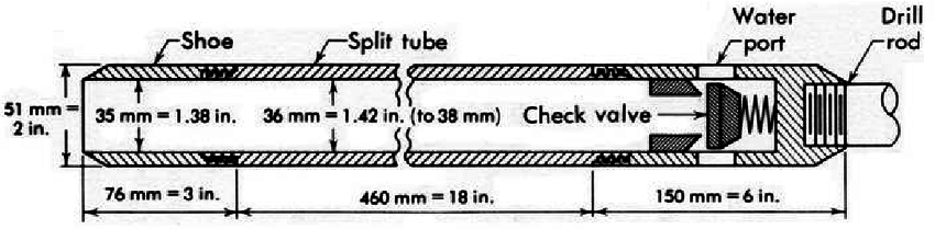
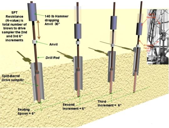
The split spoon sampler is driven into the soil a distance of 450 mm at the bottom of the boring
A hammer of 63.5 kg wt with a free fall of 760 mm is used to drive the sampler .
The no. of blows for a penetration of last 300 mm is designated as the “ Standard Penetration Value” or “Number” N
Standard Penetration Test
Cone Penetration Test (CPT)- to determine type of soil using electronic measuring system that records tip resistance and friction
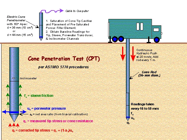
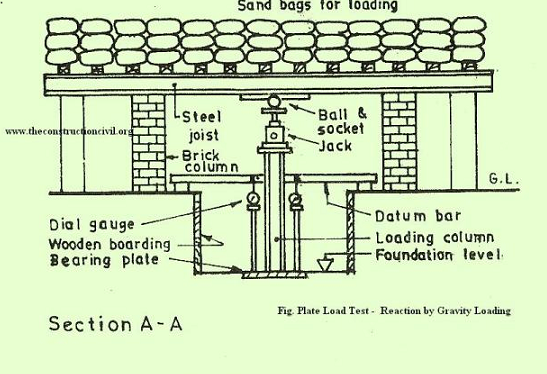
PLATE LOAD TEST (IS 1888:1982)
Plate bearing test is an important field test for determining the bearing capacity of the
foundation. In this test a compressive stress is applied to the soil pavement layer through rigid plates of relatively large size and the deflections are measured for various stress values.
Spacing of Bore Holes
|
Structure |
Minimum No of Bore Holes |
|
Check dams |
At abutment points and at 20 m intervals in river course (minimum one number in river course). |
|
Regulators |
Borehole should be taken at all pier points and abutments. (Usually the centre to centre distance between the pier is standardized to 14m |
|
Side protection Works |
If these works are necessary, bore holes should be taken on the banks at the upstream and downstream of the structure at 30 m intervals along the required length. |
|
Cut off walls. |
At positions of cut off walls , for designing Apron. |
If the Site Engineer in charge feels that there is a necessity of closer bore holes then he should execute as per site conditions
|
Development |
Test Spacing |
Approximate Depth of Investigation |
|
Dams |
25 m to 50 m |
2 x height of dam, 5 m below toe or of slope. 3 m into bedrock below toe whichever is greater. Extend into zone of low permeability. |
|
Canals |
100 m to 200 m |
3 m minimum below invert level or to a zone of low permeability |
|
Culverts <20 m width 20 – 40 m |
1 Bore hole One at each end One at each end and 1 at middle with maximum spacing of 20 m between bore holes |
2 B – 4B but below base of compressible layer |
SUB SOIL EXPLORATION REPORT
The following details should be attached to the report:
1. Latitude and longitude of location
2. Site location map
3. A plan view of the location of the borings with distance between them with respect to the proposed structure
4. Boring logs
5. Laboratory test results
6. SBC and N value of each layer
7. For rocky strata, the RQD value should also be included
8. For rocky strata, the RQD value should also be included
9. Report should be authenticated by field officers.
BENCHMARK
LOCATION AND NUMBER OF B.M
|
S. No. |
Particulars |
Standard/ permanent B.M Location &No. |
Ordinary or Temporary B.M. Location & No. |
|
1. |
Major Dam & Medium |
One on either bank along the alignment |
Dam alignment excluding river portion @10 chains located D/s at a distant of five times the head of the dam away from the C/L of the dam. One on Waste weir at a distance of 2 chains from the mid pointed of the C/L of the alignment. Spill channel & approach channel alignment one @ every 10 chains. |
|
2. |
Minor Dam |
One on one bank |
Same as for Sl. No. 1above |
|
3 |
Canal alignment |
At every 5 km along the alignment, on the canal boundary line |
At every one km along the alignment, on the boundary line excluding standard B.M.S. |
|
IS 2131-1981 |
Method for standard Penetration test for Soils |
|
|
IS 7720-1991 |
Criteria for investigation planning and layout for barrages and weirs |
|
|
IS 1892-1979 |
Code of Practice for subsurface investigation for foundations |
|
|
IS 11385-2008 |
Sub surface exploration for canals and cross drainage works |
|
|
IS 4453 :2009 |
Code of practice for subsoil exploration by pits trenches etc |
|
|
Is 4434:- 1978 |
Vane shear test (VST)- to determine shear strength of cohesive soil in its natural condition.
|
|
|
IS 6955-1973 |
Bore Hole spacing guidelines for Earth and rock fill dams
|
|
|
IS 11385,1985 |
Bore Hole spacing guidelines for canals and cross drainage works |
|
|
IS 2720 (Part 2)1973 |
Determination of water content (second revision) |
|
|
IS 2720 (Part 5)1985 |
Determination of liquid and plastic limit (second revision |
|
|
IS 6403-1981 |
Code of practice for determination of bearing capacity of shallow foundations. |
|
|
IS 1498:1970 |
Classification and identification of soils for general engineering purposes (first revision |
|
|
IS 2720 (Part 1)1983 |
Preparation of dry soil samples for various tests (second revision) |
|
|
|
|
|
INVESTIGATION-IS CODES